This repository contains the instructions to build and set up a NUS link test using the Simmel platform. It also documents the theory behind the NUS link.
NUS as a technology for contact tracing is not a good idea, because of the physics of ultrasound. Ultrasound is fairly directional (which is why bats can use it to navigate in the dark), and does not penetrate through fabrics well. At best, NUS would be awkward for users, requiring them to wear beacons in prominent locations that are hard to block, such as a lanyard around their neck.
However, the potential privacy (due to its limited range) and power benefits (due to the simplicity of the receiver) of NUS were compelling enough that we were obligated to investigate the technology further.
This "link test" repository represents the culmination of our research. While our findings generally support our initial assertion that NUS is not a great technology for contact tracing, it is, however, potentially quite useful for a number of other free-space, short-range, low-power, cheap, and entirely open source communication links.
Therefore, please regard the remainder of this README as breadcrumbs for anyone who is looking for an open source reference design for a near-ultrasound free-space link.
Simmel uses the NRF52 series of BLE chips, which natively supports I2S (a digital audio standard) and table-driven PWM synthethis. The core is also a 64-MHz Cortex-M4 with floating point ad DSP instructions.
We take advantage of these three features (I2S, PWM, FP/DSP instructions) to create a near-ultrasound (NUS) link using a Murata PKMCS0909E4000-R1 piezo buzzer and a TDK Invensense ICS-43434 direct-to-digital microphone.
The carrier frequency is 20.8333 kHz; this is above the threshold of hearing for most humans, including young children. The Murata piezo buzzer is officially characterized to 10kHz but our experience shows it is performant at 20kHz. The ICS-43434 microphone, in "high performance mode" is rated to sample at up to 51.6kHz (and thus can capture up to 25.8kHZ tones). However, due to limitations of the NRF52 (no PLL to synthesize arbitrary audio clocks), we "overclock" the microphone at 62.5kHz sampling rate and the system continues to perform acceptably.
The ICS-43434 microphone is also a particularly low power direct-to-digital microphone, and in our studies the direct-to-digital feature of the microphone puts it at a lower system power consumption than discrete ADC-based solutions, or even the on-board integrated ADC of the NRF52.
The piezo element is driven using a 3.3V rail-to-rail square wave via a pair of complimentary push-pull drivers. This allows us to run in a "bridged" mode for greater acoustic power output.
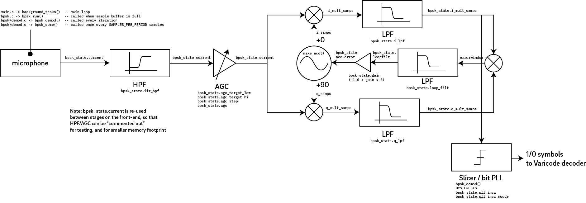
A PSK31 link using BPSK modulation scheme with Varicode encoding is used.
In a nutshell, there is a continuous-frequency carrier of 20.833kHz,
and 1 and 0 symbols are encoded using either a phase shift of 0
or pi radians (180 degrees). We had originally attempted an AFSK
scheme but found it to be too susceptible to ambient noise. BPSK is
a bit more robust to amplitude noise, yet is simple enough to implement
that we could modulate and demodulate it using a software-only DSP solution
on a 64 MHz Cortex-M4. This last constraint is significant: the high sampling
frequency and real-time requirements put a large strain on the CPU resources.
20833Hz was chosen because it is equal to the sampling rate (62500Hz) divided by 3, and it is outside the range of human hearing (just above 20kHz).
The sampling rate of 62500Hz is chosen because it is nearest frequency to the maximum frequency of the ICS-43434 supported by an NRF52 with a 32 MHz external crystal.
Because the NRF52 does not have a PLL for the system clock, you cannot divide the 32MHz reference crystal frequency fractionally. The lack of system PLL is actually important: PLLs are power-hungry, and if you want to run a receiver for months on a small battery, this is a necessary compromise. In fact, one of the reasons why the BLE radio subsystem is so power-hungry relative to the CPU core is that the RF section does have a PLL, and that accounts for a significant fraction of the passive power draw of BLE. In other words, in order to realize a potential promise of NUS (low power always-on scanning), non-standard sampling rates (e.g. not your audio standard 44.1kHz or 48kHz) are virtually a requirement.
Thus an evenly devided 4 MHz is used as the sampling clock for I2S, which is further divided by 64 (32 clocks for each of "left" and "right") to derive the base sampling rate of the ICS-43434. Note that the ICS-43434 requires a 32-clock sample period with stereo framing for proper operation, due to the way its internal digital filters are set up, even though we data on a mono channel. Also note that 32-clock sample periods are acutally not directly supported by the NRF52833 hardware; we emulate the LRCLK using a phase-locked PWM signal mapped to the pin (more details in the demodulator README) and perform byteswapping in software.
A 1 or 0 symbol is represented by 32 cycles of the 20833Hz
carrier. Thus the baud rate is 20833Hz / 32 = 651.0417 symbols per
second.
The 1 or 0 symbols are then encoded using the variable-rate Varicode
encoding, which means the actual character rate of e.g. ASCII text
varies depending upon the character.
Please refer to the demodulator
(https://github.com/simmel-project/nus-link/tree/master/demodulator)
and modulator
(https://github.com/simmel-project/nus-link/tree/master/modulator)
README files for their respective in-depth descriptions of their
implementation.
Below is an example of the demodulated data plus incoming data, measured under the following conditions:
- Modulator pointed directly at demodulator, 1 meter distance
- Music playing, measured at 50dB at demodulator device
The top trace is the demodulated data, and the bottom trace is the raw incoming samples, but normalized to be viewable (without normalization, you would just see a flat line because the incoming amplitude is actually quite small).
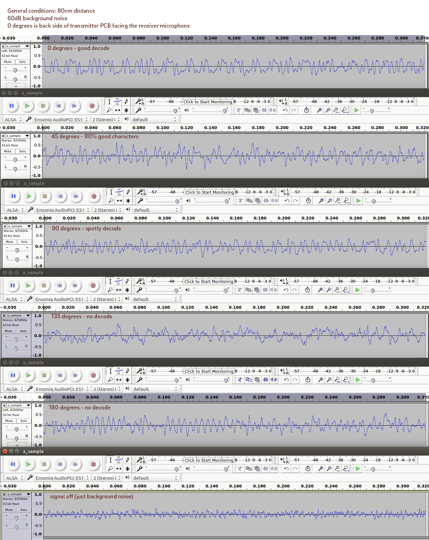
To very grossly characterize the directionality of the transmitter, a transmitter was fixed to a post 80cm from the receiver, and rotated in 45-degree increments. The peak emission strength is through the PCB (through the bottom of the transducer), and the weakest emission is from the top of the transducer.
Within about +/-45 degrees off the line of optimal power, decode performance is subjectively good. However, past 90 degrees off optimal, the demodulator is unable to achieve a lock on the signal.
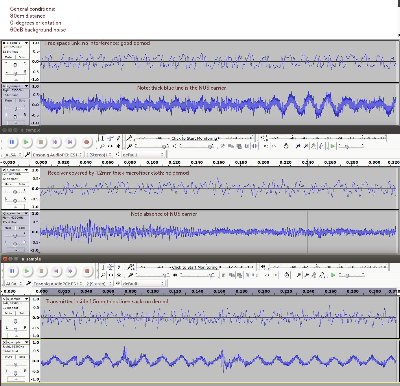
The same setup as above was used to get an idea of the impact of cloth, such as if the device were put in someone's pocket or handbag. The transmitter was fixed 80cm from the receiver, with the transmitter directly pointed at the receiver for optimal link performance. Link performance is clearly degraded when about ~1mm thick cloth is put over the receiver or transmitter. In the case of the receiver, a microfiber cloth was draped over the receiver and folded until the link was no longer working. The cloth itself is quite thin, about 0.3mm; two folds (total thickness 1.2mm) would cause the link to cease operation. Likewise, about a 1.5mm thick linen sack (a typical thickness for a hand bag) put over the transmitter also cut the link.
The images above show both the demodulator output, as well as the raw waveform going in. The NUS signal is visibly attenuated compared to the background music playing concurrently with the test.
A third test was conducted to demonstrate that NUS is unable to penetrate human bodies. The reciever was placed, once again, 80cm from the transmitter, and optimally oriented. A human test subject then stood in front of the transmitter, simulating a situation where the transmitter maybe carried in e.g. the back pocket of a user. The link was immediately lost when the user stood in front of the transmitter, and the resulting waveform is similar to the case of the 1.5mm linen sack.
Both the Tx and Rx Simmel devices show a draw of 8mA at 3.0V running 100% duty cycle modulator and demodulator loops. No attempts were done at power optimization; however, the computational complexity of the demodulator seems to push the NRF52's CPU to its limit, burning about 4-5mA to do the demodulation. Simplifying the computational loop can reduce power consumption, by allowing the CPU to idle.
The Simmel development system assumes you already have an Rpi with the appropriate adapter installed, and openocd compiled with BCM2835 support.
In order to start the openocd service, you will need to clone
the Simmel Scripts
(https://github.com/simmel-project/simmel-scripts.git) repository, and
run the swd script within. The README in the Simmel Scripts repo
will guide you through this.
You will also need to follow the directions within the
simmel-scripts repo to load the nrf52 "softdevice" firmware before
the modulator code can work. The softdevice firmware is part of the
bootloader repo.
In order to run the link test, you will need two Simmel physical devices: one to transmit, and one to receive. If you have just one Rpi dev board, this means you'll need to swap cables back and forth.


